Piecing It Together / Week 13 / Final Project

FINAL PROJECT: Mechanical Reproductions


DOCUMENTATION:

Week 1-2
Week 3


Week 4: Putting the pieces together for the final presentation
1. Painting with matte & metallic acrylic paints


2. Laser cutting last little details


3. Improvising after the laser cutter that you booked for 2 hours is broken and the one working machine is booked for everyone else’s finals and thesis projects. Went to Blick and bought a bunch of wooden dowels and a cutter. Luckily, I had some wood scraps from my mid-term project and some test printed gears, so I was able to scrape together the final details.


4. The moment that it came together, along with an illustration for the inspiration and model.


•••

NEXT STEPS:
Figuring out how to make the gears actually work together to create more movement and integrating it with the pipe line.

Piecing It Together / Week 12 / Final Project: Progress

PROGRESS:
1. Bought Materials: wood, tubing, metallic paints, gesso, 1/2″ diameter copper plumbing pipes, pipe cutter (the best cutting tool ever), marbles

2. Building 12″ x 24″ frame, laser-cutting pieces and figuring out the design to make a marble move through the pipes and system.


NEXT STEPS:
1. Finalizing Design.
2. Adding an interactive component to it, like a motion or touch sensor to trigger sounds.
3. Painting and piecing it together.

DESIGN INSPIRATION: Zachmann Kinetic Sculpture, Soundtrack


THE PIECE…so far with 1 week left to finish

Piecing It Together / Week 10 & 11 / Proposal and Sketch for Final

PROJECT: Mechanical Reproductions

DESCRIPTION: Using Francis Picabia’s collage, Very Rare Picture on the Earth (1915) as a blueprint and building a 3D version using the laser cutters, the CNC router and 3D printers. Also planning on adding a moving mechanical feature to it using gears and marbles or ball bearings.

• • • • •
INSPIRATION: Francis Picabia’s machine paintings that were on display at the MoMa’s Francis Picabia: Our Heads are Round so Our Thoughts Can Change Direction exhibit and a past ITP project, Visualizing Time: A Marble a Minute.
• • • • •
STEP #1: The Sketch
I sketched Picabia’s painting in Illustrator keeping in mind that this 2d vector drawing would be laser-cutted and possibly 3D printed for some parts. I wanted to build a drawing of a structure from scratch that symbolizes a working system (ex: filtration of data or the human body), but I found it helpful to replicate and work off Picabia’s design. I will eventually adjust things to make the gears and tubes more functional to create movement of a ball or marble inside.
• • • • •
STEP #2: Materials
  • Base/ Frame: To create the base and frame by layering wood on top of another and cutting it on a laser printer or using the CNC machine.
  • Cylindrical Pieces: Using the CNC machine to make the cylindrical pieces.
  • Gears and Flat Pieces: Laser cutting them from wood and adding metallic colors of silver and copper to make them more metal-like.
  • Metallic Finishes: Going to look into gold leaf or patinas, but bought some metallic paints to also test on the wood.


Piecing It Together / Wk 9 / 3D Printing

FINAL DESIGN: 3-piece puzzle of a tree maze (Top Cover,  Middle, Bottom)

FEATURES:
– 2 player game to race against one another
– Pieces can interlock together and contain metal ball bearings for the game
PROCESS:
After we figured out the design for the tree maze, our next steps were to see how our design would translate into the 3D print using the LuxzBot Taz and UltiMaker machines.
1.) INITIAL 3D TEST PRINT: In order to see how the specs would translate to the printed form, we printed our initial design file that we were playing with. We were able to figure out how to take the Tinkercad file, save it as a (.stl) file, load it into Cura to create the (.gcode) file, and then transfer (.gcode) file to an SD card to print on the LuxzBot Taz machine. The total print time for this piece was 2 hours. The main problem from that we ran into with this test run was the depressions printed raised lines, so the extruded parts of the opposite piece could not interlock to close.

TEST PRINT
2.) MAKING ADJUSTMENTS: We needed to adjust the files to make the depressed line strokes thicker and deeper so the walls of the maze could fit right in. Also from class feedback after showing our sketch in class, one suggestion was to make the maze more in-tune with the concept of a ‘tree’, so Jenn made the lines inside the maze more branch and leaf-like.

NEW TREE DESIGN


CURA VIEW – 3 pieces (bottom, middle, top)


3.) 3D PRINTING PROBLEMS: We made the pieces smaller hoping to lesson the print time, which for this job was estimated at 3 hours. The problem with this was that the pieces were lifting off from the bed and moving around. We tried printing these files a couple times by making the file bigger and waiting for the machines to cool down. During these trials, we noticed that the different color plastics also affected how hard and soft the 3D piece was. We had more success printing with the opaque white plastic, as opposed to the clear and black plastics that were more flimsier.

Prints lifting and moving from the bed

Many failed 3D printing jobs


4.) RAFTS AND BRIMS: While trying to solve the problem with the plastic lifting from the bed, we tried adding a raft and a brim in Cura to help keep the piece down as it printed. It still didn’t work well on the LuxzBot Taz, but when we used the UltiMaker machine, the print was able to finish without lifting off from the bed. 

Printing on Ultimaker with raft around design

Piecing It Together / Wk 8 / 3D Puzzle

GROUP
Jennifer Tis
Anne-Michelle Gallero

………

IDEA
To create a 3D maze in the shape of a tree on either the 3D printer or on a wood panel using the CNC machine.


………

INSPIRATION

WOODEN MAZE ON WESTWORLD


MORE EXAMPLES OF WOODEN PUZZLES

………

PROCESS
1. After collecting some photos and links of 3d mazes and puzzles that we liked, we decided to continue with the maze idea as either a 3D printer object or using the CNC machine after seeing some examples of wooden mazes online.

2. Created a maze from a puzzle  generator online: mazegenerator

3. Started building the 3D version in Tinkercad and figured out that we could build the object in Illustrator and then import it in Tinkercad as a SVG file.


4. Initially, we were having problems importing the file because Tinkercad would disregard the complex shapes with grooves and simplify it into a filled-in piece. We needed to create the twists and turns of the shape as an object instead of a stroke. Attempted to rebuilt the maze from scratch in Illustrator to turn all the lines into a combined object (and not just lines).

 
5. Needed to find a simpler and faster solution of taking the stroke and turning it into an object… and after doing a google search, discovered “EXPAND.”  By applying the “EXPAND” feature in Illustrator, it turns the stroke into an object.
 
6. Importing the new SVG file into Tinkercad: The Tinkercad program still filed in the shape as a solid piece, so opened the SVF file in Fusion 360 and it maintained it’s original shape in there.


7. Next step will be to prototype and test the design on a 3D Printer.

Piecing It Together / Wks 5 & 6 / Gear Box Midterm

WEEK 5  (Prototype)
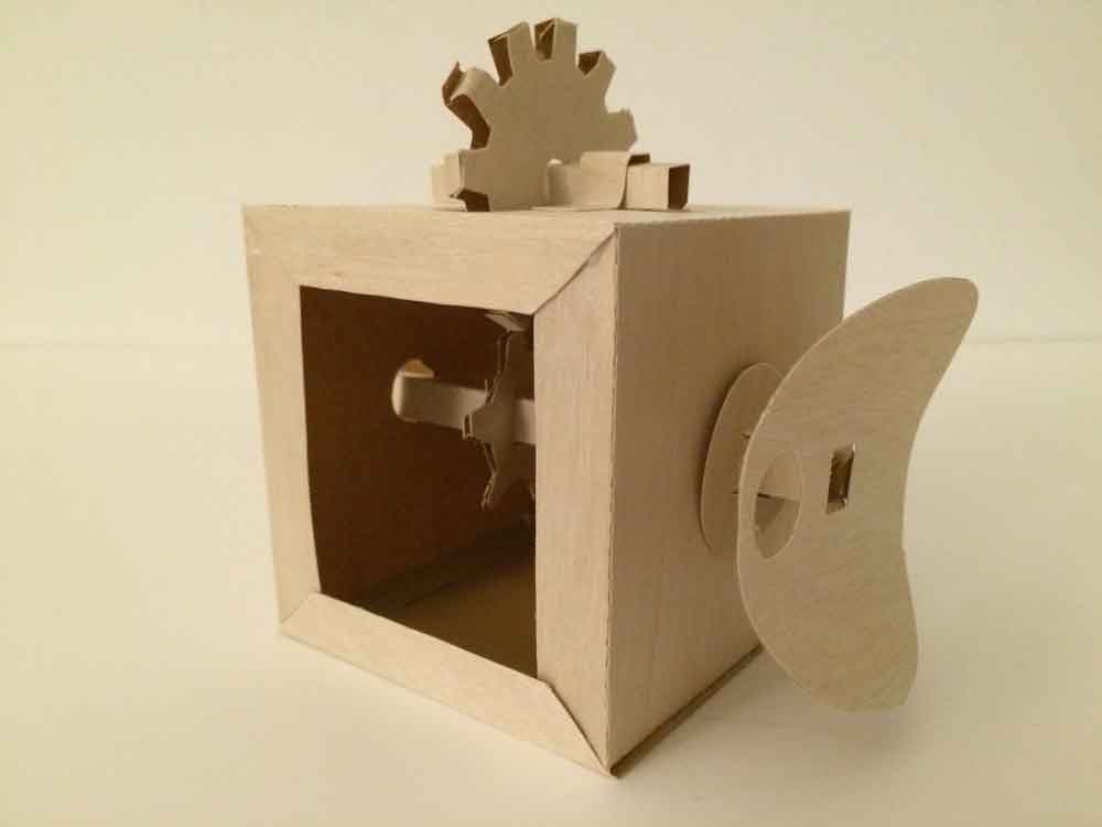
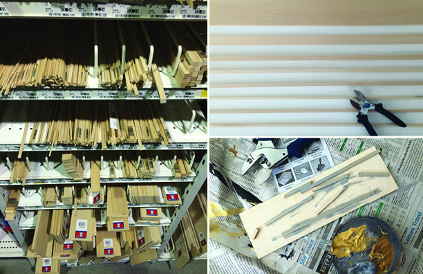
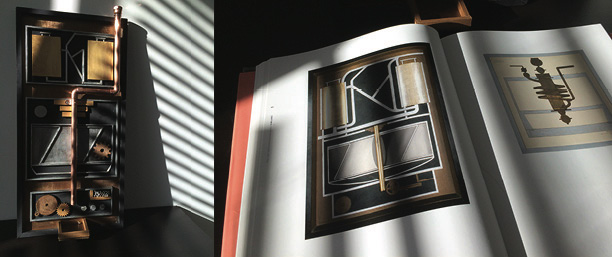
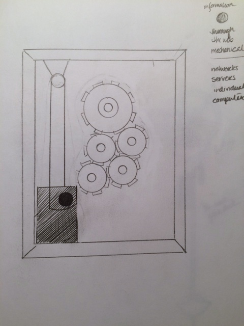
I decided to focus on the Karakuri mechanical box, so I can explore the mechanics of gears and translate the paper form to a wooden version. To help me get started, I used the paper templates from the book, Karakuri: How to Make Mechanical Paper Models Move. I was able to cut and assemble a paper model of the box and gears as the start of my prototype.


• • • • •
WEEK 6  (The Construction)
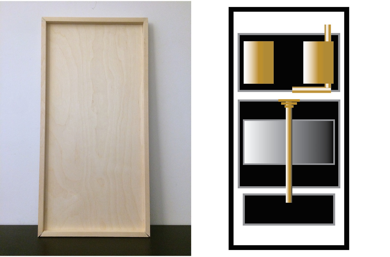
The next steps for me was to draw the flat pieces into a digital vector format so I could easily adjust the pieces into an updated design using wood with a 1/4″ thickness.

1) Taking the box apart and measuring the individual pieces to translate them into a vector form in Adobe Illustrator. (TIP: When I used a regular ruler to measure, it was a little frustrating to get precise measurements. Instead, I used a precision ruler that I’ve had for years to help me measure the exact fractions. And when I need to convert the fractions to decimal points quickly, I keep a conversion chart of fractions to decimals by my desk and in my sketchbook.

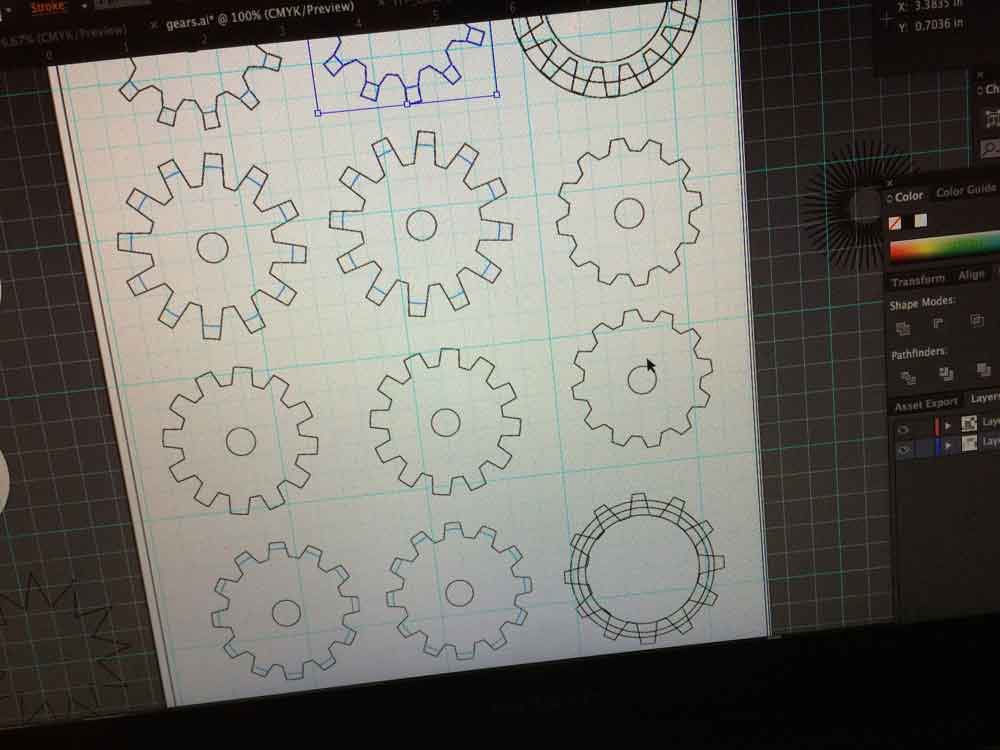
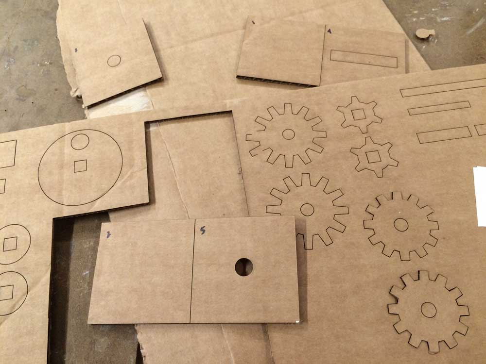
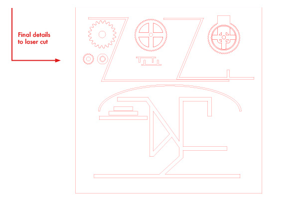
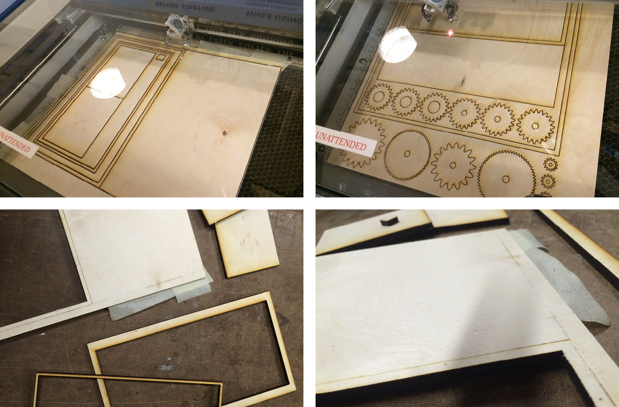
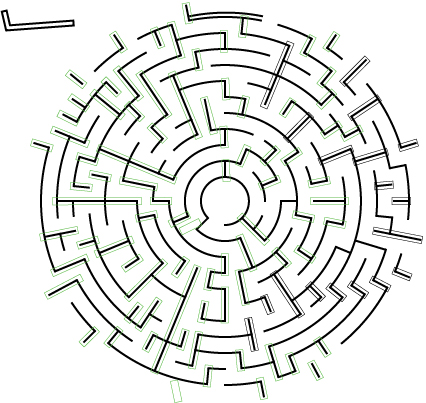
2) Template in Illustrator and making gears:  I struggled with drawing the gears but after watching some YouTube videos, I figured out some quick and less frustrating tips in gear making. Start with 2 circles (diameter, diameter with length of teeth), then a star (to help guide the placement of the teeth), use the ‘Outline’ tool in the ‘Pathfinder’ tab, ungroup and set the stroke to Black, and delete the lines that are not needed.

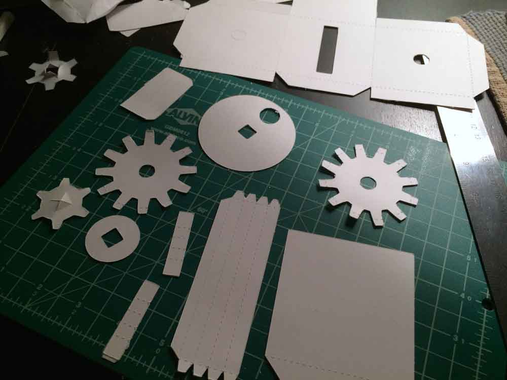
3) Testing the template on a vinyl cutter: I tested the template on a vinyl cutter first. This helped me correct template by adding or removing lines that should of been cut versus needed to be perforated. Adjusting my template before trying the template on a laser cutter definitely helps save time. When using the vinyl cutter, I first started off with 100# Bristol paper which required a deep cut blade and I experimented with cutting the template on wood paper as well. The wood paper has a nice finish, but it’s too flimsy and the vinyl cutter didn’t cut all the way through so I needed to over the edges with an Exacto knife. I also need to figure out the correct settings to get the vinyl cutter to cut through thick sheets—I had the same issue with the 100# paper stock.
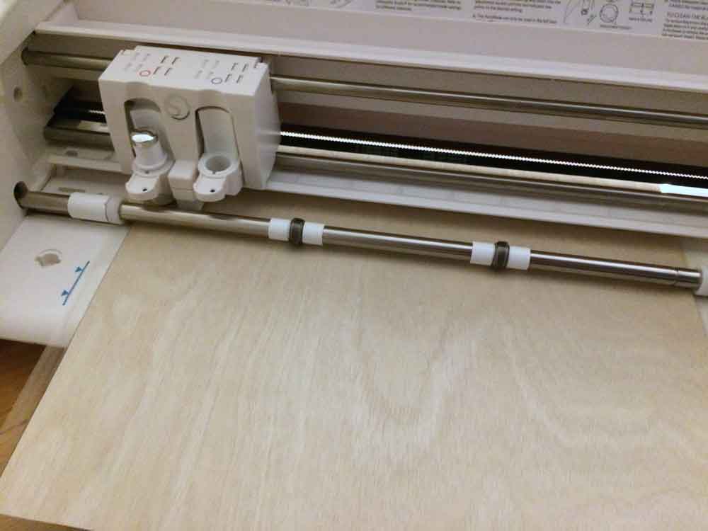
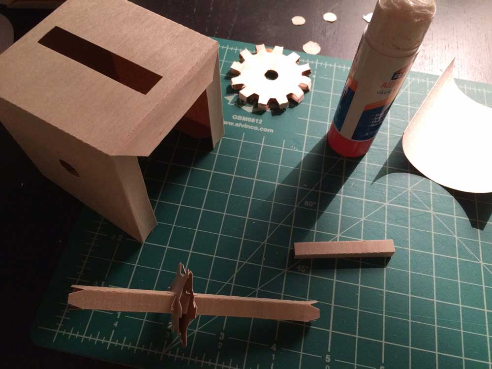
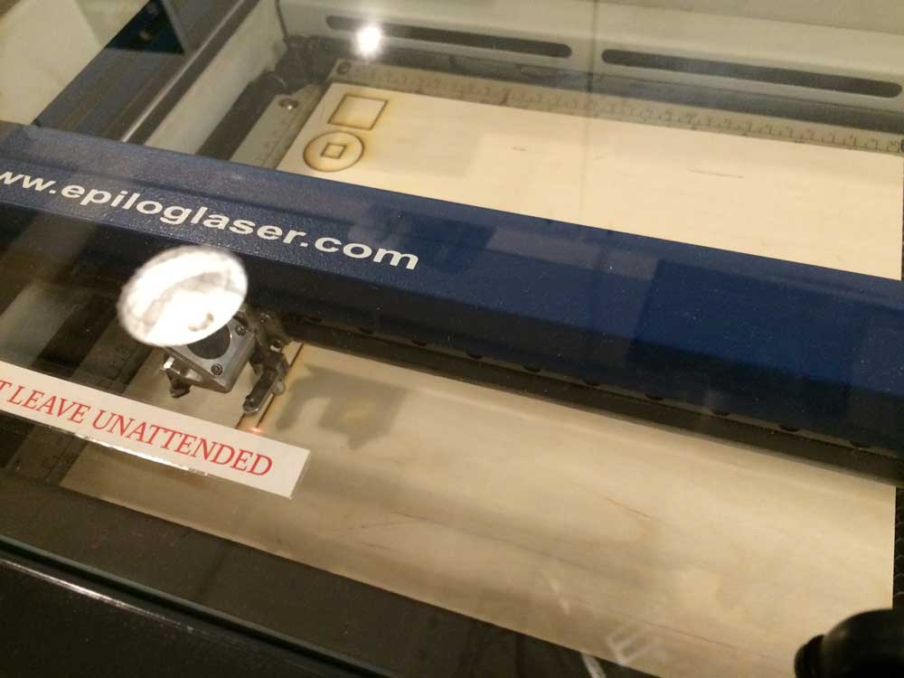
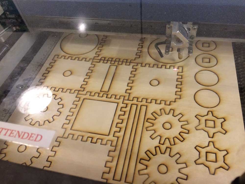
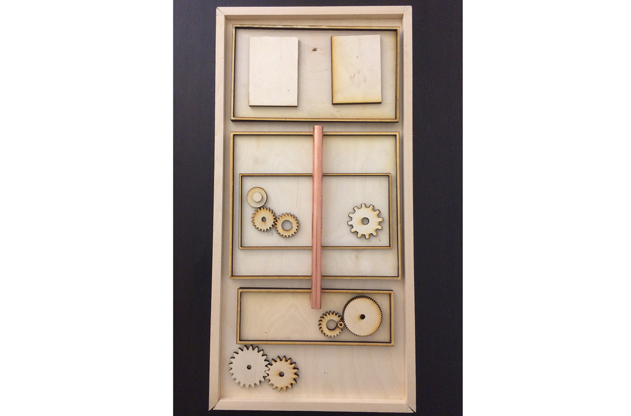
4) Testing the template on the laser cutter and more prototypes: Translating the flat pieces to something that has depth, particularly the 1/4″ thickness of the wood. I first tried cardboard and then wood. The challenging part of this task was recreating the box without the paper flaps. After seeing a rough prototype of the wood version and how I glued it together, the thickness of the wood added to the length of the cube and if I glued it that way,  I would need to make some ‘sides’ shorter in order to compensate for the added depth.  (NOTE: the laser cutter didn’t go through the wood completely after 3 passes and needed to run through the laser cutter a couple more times to cut through the wood. Also book enough time to do this.)

5) Constructing Boxes with Interlocking Edges: I actually tried to construct this last semester for my 
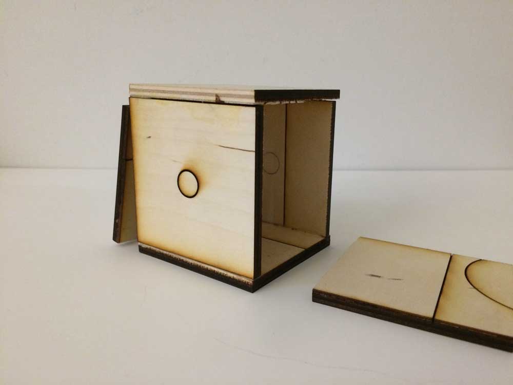
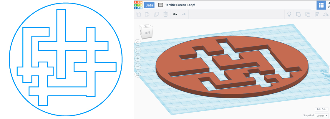
PCOM midterm (and before I learned how to use the laser cutter), but I couldn’t get the grooves to match perfectly and ended up buying an acrylic cubed enclosure from The Container Store. I tested a rough version on cardboard with the laser cutter first, but ran into the same problem of figuring out where things should interlock, so I carefully worked on laying out the  interlock in Illustrator and spacing the grooves apart by 1/4″ (which is also the same size as the wood thickness).  In Illustrator, I also laid out each side of the box like a cross so I could easily see what was connected to what and tested the grooves next to one another. After each round, I tested a paper version on the vinyl cutter a couple times, taped the pieces together and was able to mark with a Sharpie, what grooves were unnecessary or missing to adjust my template.

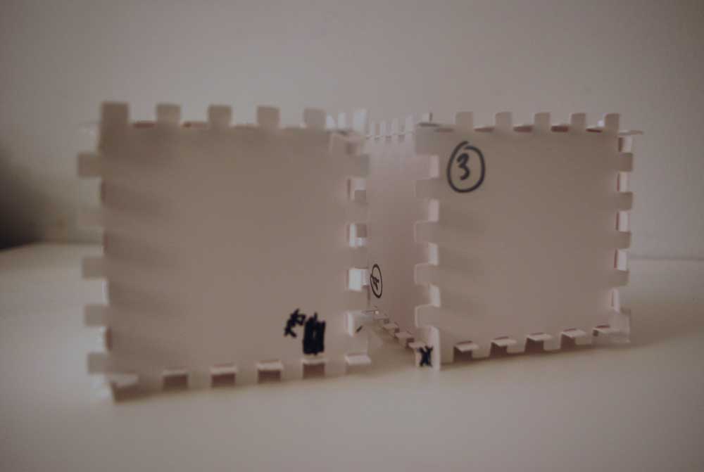
6) Laser cutting with the final template on “wood”: For this latest version, it took an 1 hour to do 9 passes through the laser cutter. It did cut through to almost everything except for 2 gears with the longer teeth, which were luckily my backup pieces that I didn’t need). I was very happy that the sides interlocked with no missing pieces and decided not to use wood glue to lock them together cause the interlock fits tightly together. On my template, I tried to keep the pieces interlocked while it was laser cut, so the sides would fit together smoothly when constructing the box.

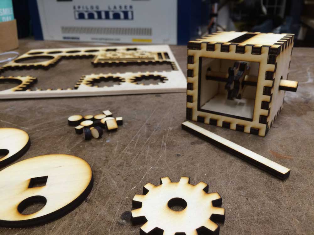
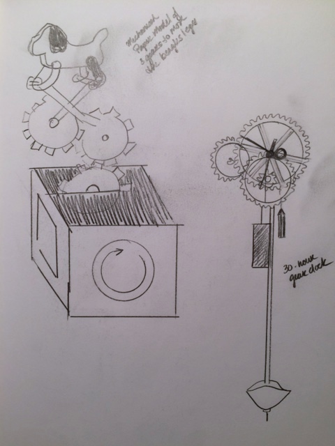
7) Work in Progress: In order for the gear mechanism to work better, I need to make the holes (or squares) in the center of the inside gears and the big circular ‘turner’ smaller and the long beam a little thicker, so it has more tension and doesn’t allow the gear to slide around as much. In the paper version, there were small paper tabs to glue onto the beam to keep things in place. By making the holes a little tighter, I’m hoping that it will keep things in place better. I also want to add a top piece to the box and attach it to the gear mechanism. I was thinking of trying to animate the wheels of a Mars Rover and have little human figures inside the ‘gear’ box, standing on and around the gears to convey the idea of them controlling the Rover’s “movements.”

Piecing It Together / Wk 4 / Midterm Sketches

For my midterm project, I was thinking of creating a mechanical piece of artwork inspired by Francis Picabia’s Dada Movement drawing. I want to reinterpret it in today’s fast paced information age of social media and the internet using wooden gears and pulleys in a 8″ x 10-7/8″ space. This would be an exercise for myself in making a physical and moving editorial illustration.

INSPIRATION: Francis Picabia’s drawing on the Dada Movement

• • • • •
Below are my initial sketches and in doing these, I realized that I need to research the topic more to map out the system. I also got a couple of books (Karakuri: How to Make Mechanical Paper Models That Move and Making Wooden: Gear Clocks) to help me understand how gears work and the workings of a clock. If all else fails with my initial idea, my fall back plan is to do to something more straightforward like a Karakuri piece or attempt wooden clock making).

SKETCH 1: Initial Idea

SKETCH 2

SKETCH 3

SKETCH 4

SKETCH 5: back-up plan

Piecing It Together / Wk 2 / The Box

GROUP
Sejo Vega-Cebrián
Anne-Michelle Gallero

………

IDEA
Inspired by the shape of a Rhombicosidodecahedron, we were thinking of making a turtle-box / box-turtle of paper and planned on reverse-engineering it to make half of it as the shell of a turtle. The bottom part with be a smaller shape, so the shell can cover it and work as a lid.

………

INSPIRATION

………

SKETCH

………

PROTOTYPES

#1 –  First attempt to structure the box


#2 – Second attempt at building the template. This will be the bigger top half template and for the smaller bottom half.


#3 – Paper Cutouts to test the template.